
|
Videos from the Delta Queen when it was a working steam powered boat. 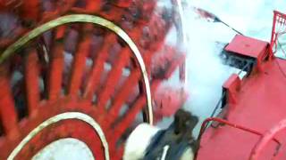 Paddlewheel turning I Paddlewheel turning II Paddlewheel turning and wake Rain on the river and paddlewheel 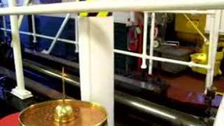 Inside the engine room 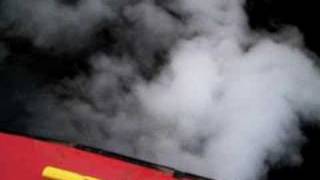 Letting off steam in a lock 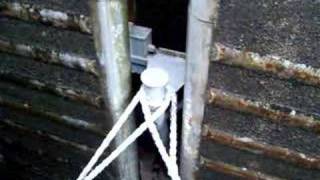 Rising in a lock Delta Queen idles in a lock A Short History of Steam Engines by K. Spitzner, Georgia The Plain Cylinder Boiler 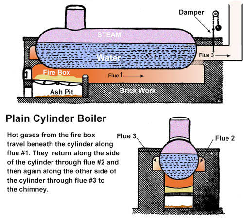 The first real advancement in boiler design came about with the invention of the Plain Cylinder Boiler. It was a simple design and easily constructed. As its name implies, the Plain Cylinder Boiler is a long metal cylinder with conical (round) ends set horizontally in a brick work. Some of these boilers were 40 feet long. The cylinder was half filled with water and a fire ignited in furnace at one end. The fire and hot gasses are first channeled from the furnace along the bottom of the cylinder to the opposite end of the boiler. This channel is called a "flue" and is made of brick on three sides. The other side of the flue is the metal wall of the boiler. The fire and hot gasses touch the bare metal and heat the water inside the boiler. When the hot gasses get to the end of the first flue, they are channeled back along one side of the cylinder to the front of the boiler. From there they are again channeled back along the other side of the cylinder to the chimney. This would give a boiler 40 feet long 120 feet of heating surface. The speed with which the fuel burned was controlled by a damper near the chimney. Raising or lowering the damper controlled the draught or amount of air being drawn into the furnace. More air made the fuel burn faster and hotter making more steam. Less air saved fuel and produced less steam. Although this boiler design was far more efficient than previous boilers, and had been used for more than one-hundred years, it had two major flaws. The first was dirt. Water, especially Mississippi River water, contained dirt and this dirt remained in the boiler after the water evaporated. After a time, this dirt collected in the bottom of the cylinder and acted like an insulator preventing the heat from reaching the water. This means that more fuel had to be burned to get the same amount of steam. It also meant that the boiler had to be cleaned out very often. The second flaw was more dangerous. As the hot gasses traveled along the 120 foot long flue, they cooled somewhat. Not much but enough to cause the metal of the cylinder was heated to different temperatures on either of the three sides. This uneven heating of the metal caused great stress within the metal which often led to the cylinder exploding. The Cornish Boiler 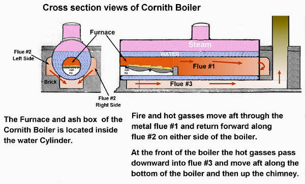 William Wycherley said it, "Necessity, the mother of invention." The invention of a workable steam boiler and engine made mass transportation possible. However hazardous it might have been. Economics and the need to get the cargo safely to a destination was the driving force behind new designs for boilers. The passengers also enjoyed arriving, in one piece. Development of the Cornish Boiler was a step in that direction. Until that time designers had always placed the furnace beneath the water cylinder. Attempts to make use of the heat that was going up the chimney were limited to simply rapping the hot gasses around the boiler several times. Them some genius had the idea of putting the fire where it would do the most good, in with the water. Not actually "IN" the water but literally inside the cylinder containing the water. The Cornish Boiler made several design changes. First, as I already said, the furnace was placed inside a metal tube measuring three(3) feet or more in diameter (from side to side). And this tube was placed inside the boiler. Having all that hot metal inside the water greatly increased the amount of heat transferred to the water. Like the Plain Cylinder Boiler, the fire and hot gasses were still routed through three flue's which run along both sides and beneath the cylinder. But unlike the Plain Cylinder Boiler, the order in which the gasses moved was changed. After leaving flue #1 (the metal tube running through the water) the hot gasses were divided at the aft end and moved forward along flue #2 which runs along both sides of the cylinder at the same time. At the front of the boiler the hot gasses were directed downward into flue #3 and traveled aft beneath the boiler to the chimney. This helped reduce the amount of mud that accumulated in the bottom of the boiler and that increased the boilers efficiency even more. The flat ends of the cylinder are another obvious design change made necessary by the internal furnace. What is not so obvious from in the illustration is the size of the boiler. Unlike the Plain Cylinder Boiler, the Cornish Boiler is quite a bit larger. It holds less water than the Plain Cylinder Boiler but transfers heat to that water at a much greater rate producing more steam, at higher pressures, in a shorter time. Fuel efficiency was just as important in the 1800's as it is today. All these improvements came at a high price for the designers did not take into account the effects of heat expansion on the metal flue. The internal tube with its furnace and fierce heat was constantly changing length. When heated the metal tube would expand several inches causing the ends of the boiler to bulge outward. As the furnace used up the fuel in the fire box, the temperature would drop slightly. Not a big drop in temperature but enough to allow the metal tube to contract. After more fuel was added the tube would heat up again and cause another bulge in the ends of the boiler. This constant back and forth movement placed a great amount of stress on both ends of the boiler. The result of all that repeated back and forth stress was something called a, "collapsed flue." Which is just another type of boiler explosion. The results are the same. If you twist a wire coat hanger back and forth many times you will see just what happens to the metal, without the big explosion. Boiler explosions were common. Way to common in those early days of steamboats. But progress was being made in boiler design both in efficiency and safety. The Lancashire Boiler 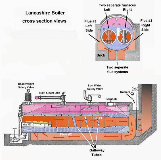 The need for smaller more powerful, to say nothing of safer, steam boilers finally led to the Lancashire Boiler design. Basically the same as the Cornish Boiler with its internal furnace design. But vastly improved both in efficiency and safety. The first advance was in the number of furnaces. Each boiler had two completely separate furnaces sitting side by side. And each furnace had a separate flue system. At first this might seem silly yet the idea behind having two separate fires going at the same time is outstanding. Everything that burns, wood and coal especially, contains some amount of water and that water must be evaporated before the fuel will burn efficiently. In the time it takes the fuel to be heated, the furnace cools somewhat and that in turn lowers the amount of air being drawn into the furnace. The less air drawn in the less heat created in the furnace. And as I said in the article on the Cornish Boiler, this slight cooling allowed the metal flue to contract placing a heavy strain on the ends of the boiler. It also slowed the heating of the water inside the boiler reducing the amount of steam available. With the Lancashire Boiler each furnace is stoked at a different time. This means that one furnace is always producing maximum heat and that heat creates a powerful draught in both furnaces speeding up the ignition process. Something like blowing on a campfire. It heats things up real fast. It also means that more air is drawn into the system which allows combustion (burning) of the smoke created by the "low" burning furnace. This combustion takes place in flue #2 thereby increasing the amount of heating of the sides of the cylinder. Having one furnace always at full heat also provided a more even tension on the end plates as one flue was always fully expanded. Like the boilers we have already seen, the Lancashire Boiler has three flues. The first is the metal tube which runs through the water in the boiler. From this the hot gasses moved downward beneath the boiler through flue #2 and then aft again along side the boiler in flue #3 to the chimney. But the Lancashire Boiler is designed with two separate flue systems. Gasses from the right side furnace remain on the right side of the boiler while hot gasses from the left furnace remain on the left side. They do not combine until they reach the base of the chimney connection. This system provided a very powerful, even and constant draught in both furnaces. Another major improvement in heat transfer and fuel efficiency was the addition of "Galloway Tubes". Hollow metal tubes which traverse (connect both sides of ) the main flue #1. Water in the boiler flowed through these tubes which are subject to heating by the hottest fire and gasses which pass around them. The number and arrangement of these tubes varied with the individual manufacturer. Those shown are typical and used to give you the idea of how they worked. Galloway Tubes also acted as "stiffeners" greatly strengthening the main flue (flue #1) against collapse. As I said above, the use of Galloway Tubes increased the heat transfer to the water and that of course, made more steam and made it quicker, and at greater pressures. A working steam pressure of 175 psi ( pounds per square inch ) was common. These higher steam pressures allowed for smaller more efficient engines and greater speeds. And that of course led to steamboat racing, which is another story altogether. The increased efficiency of Lancashire style boilers also allowed them to be smaller. Commonly only seven feet in diameter (side to side) and twenty-seven feet long. A great saving of both space and weight. Another advantage to the Lancashire style of boiler was the extensive number of internal braces designed to keep the cylinder from rupturing. As seen in the illustration, besides the Galloway Tubes criss-crossing the main flue, a number of metal rods extended through the cylinder and were bolted at each end. Even more, the designers placed several "gussett stays" (triangle metal braces) at both ends of the boiler. These, the rods and gussett stays, kept the ends from bulging and added much to the overall strength of the boiler. Yet even the best designed boiler cannot withstand the tremendous pressures created when the water level inside the boiler is allowed to get too low. Should the water level drop below the top of the internal flues, the intense heat of the furnace would quickly burn through the metal. And that would lead to the very unpleasant condition know as the boiler explosion. A massive steam explosion that could, and often did, completely destroy the entire steamboat and those aboard her. To help avoid this type of accident someone invented the automatic "low water safety valve" shown in the illustration. A simple enough device which would release excess steam pressure through a pipe when the water level dropped to low. The noise this valve made when it opened would also get the attention of the engineer very, very, quickly. The low water safety valve was operated by a float which rides up and down with the water level in the boiler. When the water dropped below a predetermined level, the valve would gradually open and release steam pressure. The lower the water level dropped the more the valve would open. But even this device could not handle all the pressure which would be created by a sever loss of water in the boiler. A second "Pop Off Safety Valve" can been seen in the illustration at the front of the boiler. These valves operated on steam pressure alone. Each boiler was equipped with at least one of these safety valves and most often several of them depending on how large the furnace area was. When the pressure in the boiler exceeded a specified amount, these valves suddenly "popped" wide open and stayed wide open until they were reset or replaced. Something of a chore requiring the boiler to be shut down and cooled enough so a man could work on top of it. Details of both types of safety valves will appear at this web site when I can finish illustrating them. You might also want to think about just how the engineers got water into a working steam boiler? The Upright "Fire Tube" Boilers 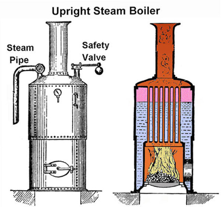 So far in this short history of the steam boiler we have looked at how the horizontal boiler developed. But here I must take a side track and explain something about the vertical (upright) boilers worked. If I don't you may not understand how the next boiler works. The term "Fire Tube" accurately describes the basis of this boiler. The water tank or boiler is a vertical tank not a horizontal cylinder as in the other boilers already described. Like the Cornish and Lancashire boilers the furnace is located inside the water tank. At the bottom of the tank where it is surrounded by water on all sides except the bottom. But take note, there are a number of brass tubes which extend through the boiler to the chimney. Depending on the individual manufacturer, there could be as many as 100 of these tubes. These tubes allow the products of combustion (flame, hot gasses and smoke) to pass directly through the boiler allowing an extremely high rate of heat transfer to the water. In other words, the fire passed through the tubes, hence the name, Fire Tube Boiler. But the extremely hot gasses made only one pass through the boiler so this design is not as efficient as those that route the heat back and forth. Much heat was wasted going straight up the chimney. Their compactness (small size) and the speed with which they developed a working steam pressure was of major importance. In the 1800's they were found everywhere. The relatively low pressures developed by this style of boiler made it perfect for many jobs. From heating a home to powering small steamboats. There were other uses for this design which you may have seen in old photographs. Upright Boilers were quite common and would usually found on small horse drawn wagons, at fires. You may recognize the picture below as one of those more common uses of the Upright "Fire Tube" Boiler. 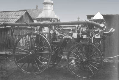
The Scotch Boiler 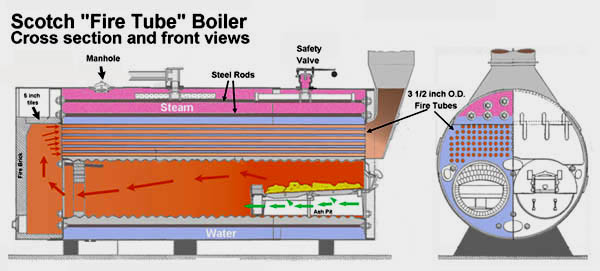 Engineers and designers of steam boilers had long understood the relationship between the amount of heat generated in a furnace and the ability of water to absorb that heat. Basically, the larger water surface exposed to the heat the more heat is transferred to the water. Like the Cornish and Lancashire boilers, the Scotch Boiler utilizes internal furnaces with the primary flue traversing the lower portion of the water cylinder. Yet unlike the Lancashire boiler, the Scotch boiler does not utilize Galloway tubes to increase heat transfer or strengthen the flue. Instead, the designers choose to manufacture the water tank from corrugated plates. The end plates are reinforced by heavy "Through Bolts". This combination of through bolts and corrugated plates provided an extremely strong boiler. Like the Vertical Boiler in the previous illustration, the Scotch Boiler is a "Fire Tube" design. In this case a number of relatively small (3 1/2 inch diameter) metal tubes pass horizontally through the water cylinder and act flues. A boiler 10 feet in diameter and 20 feet long would normally contain 137 individual horizontal tubes. These "fire tubes" were arranged above the furnaces, but below the water surface. As with the previous illustrations, fire and hot gasses pass from the furnace through the main flues which are surrounded by water. At the aft end of the boiler the hot gasses entered a chamber, or "Dry Back," which allowed the end plate to be heated and also directed the gasses into the fire tubes. From there the hot gasses moved forward through the numerous tubes to the chimney. The Scotch Boiler was quite versatile. Designs were built to deliver anywhere from 6 to 300 BHP (boiler horse power). The largest were 10 feet in diameter, 20 feet long and contained four furnaces. The illustration below shows a Scotch type boiler with two furnaces. One author says of the Scotch Boiler, "Their quick steaming ability and compactness make them particularly adaptable to marine and industrial use..." Yet even this design contained some fairly large flaws. Water circulation within the boiler was poor allowing cooler water to settle at the bottom of the boiler and remain there. This un-circulated water acted quite like an insulator decreasing the efficiency of the boiler. It also allowed mud and scales to be deposited on the outside of the main flues. This accumulation amounted to an ever increasing insulation effect which lowered the heat transfer to the water. But it also meant that the metal tubes were not cooled adequately by the water. Eventually the insulation effect would allow the metal to heat to a point where it would "plasticize", (loose its strength) and begin to bend. Engineers had to maintain a constant vigil on the condition of their boilers, to prevent a collapsed flue, or boiler explosion. Most did, many didn't and the results can be found in history books. To fix the problem of poor water circulation, designers added a rather large "steam and water drum" above the boiler. The modified unit became known as the Brady Scotch Boiler. Another disadvantage of the Scotch design, as far as western steamboats are concerned, is their size. But keep in mind that the term "marine" as it was used then, and now, refers not steamboats but steamships. Deep water, ocean going vessels which have lots of room for such things as boilers. Still, some western steamboats did use this design. And lived to tell about it. The Scotch boiler's self-contained design drastically reduced the quantity of bricks used for support and flues. Less bricks, less weight and therefore less draft of the boat. Or, looking at it another way, the more cargo a steamboat could carry and the more profit for the owners. 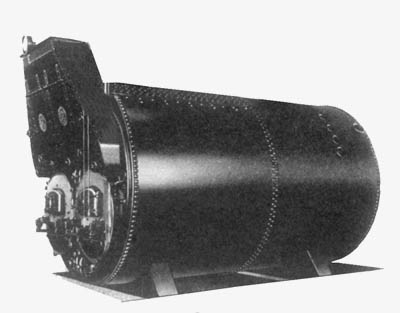
Maintaining Water Level Once the furnace had been lit and the steam boiler brought to operating pressure, the engineers job was to maintain it in that condition. Obviously this meant adding fuel to the furnace to keep a hot fire burning and replacing water in the boiler which had been used to power the engines. But how did the engineer's know when to add water, and how much should they add? Letting the water level drop below a safe level courted disaster, while adding to much water would drastically reduce the efficiency of the boiler. It was a ticklish question and one originally solved with typical river boat ingenuity. 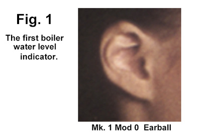 As shown in Fig. 1, each engineer would simply listen to the sounds made by the boiling water. By listening closely he could hear dull metallic rumbling sounds coming from deep within the boiler. Something akin to the noise a pot of boiling water makes on a stove. The higher the pitch, or noise, the lower the water level. It was his judgement and his alone that determined when, and how much, water to should be added. This was an extremely crude method fraught with difficulties. Consider first that each boiler made a slightly different sound. Also compounding the problem was the amount of mud which would accumulate on the insides of each boiler. The more mud, the less sound was transmitted to the outside. And what of the engineer who had a head cold or an ear ache? Was his hearing effected? A better method was needed and needed quickly. 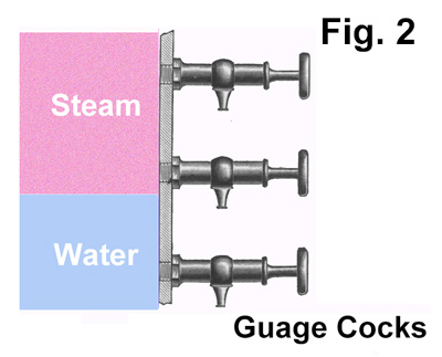 The solution, as seen in Fig. 2, was quite simple. The designers just add three "check cocks" (small valves) at the rear of the boiler. Why at the back end of the boiler? Because all the available space at the front end was taken up by the furnaces and chimneys. The front was also the scene of much actively with men constantly stoking the furnaces and removing ash from the ash boxes. Three cocks were placed one above the other with several inches between them. The exact distance between cocks was determined by the designers who knew precisely where the individual water levels were for each boiler. And each boiler design was different from all others in that respect. To find out how much water was in a boiler, the engineer had but to gently open the a cock and see what cane out. Still, as with anything as simple as opening a small valve, there was a particular method of accomplishing the task. The bottom cock was always opened first and the engineer expected to see a small jet of water issue from it. If he found steam coming from the cock and not water, he knew immediately that his boiler was running Dangerously Low of water. If water came out, very hot water, he knew he was not in any danger from low water. After closing the first, the lowest, check cock, the engineer would proceed to crack the middle cock. Here he knew he could expect to find either water, or steam, or a combination of both. In the range of this valve was the normal operating water level. Again, if only water came from the open cock, everything was alright. If steam came out it was time to add water. If a combination of water and steam blew out, well then it was up to the engineer whither or not to take any action. And if only water flowed, the engineer knew he had enough water to work the boiler safely. Adding feed water was simple enough, most of the time, but required constant monitoring. After adding water to the boiler for a short period, the engineer would again open the middle cock to determine if he had added enough water. Again, if steam came out, he would continue adding water. He would continue this process until water appeared from the middle cock. Opening the top check cock should always, always mind you, result in finding steam. If water came from this check cock, he knew the boiler contained too much water and was not operating at peak efficiency. This situation could be fixed by opening a drain valve and letting a bit of water out of the boiler. And the reason for opening the three cocks in the correct order? Simple. The bottom cock would give instantaneous notice of an extremely dangerous low water situation. Ah, and it would also drain its contents on the deck below. The second valve would drain its contents, hot water or live steam on the cock below it. Needless to say, that handle would become quite uncomfortable to hold on to after a blast of 300 degree steam. Get the picture? Now although this method of determining the water level was far better than trusting the safety of the boat to someone's hearing, it was still a matter of guess work. The true water level was always somewhere between the three check cocks but precisely where was anyone's guess. And how long one waited between checking the different cocks was pure guess work. But it did make life interesting, if not something of a gamble. There had to be a better way! 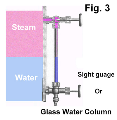 Shortly thereafter the fellows with the pencils designed that better method. A simple clear glass tube was mounted between two shut off valves which were connected to the rear of the boiler by pipes. When both valves were opened, the tube would fill with water and steam. The surface of the water in the tube would be precisely at the same level as the water in the boiler. No more guessing, just look at the Sight Gauge and know in an instant how much water she was holding. Of course Murphy's law dictates that if something could go wrong, it surely would and in the case if sight gauges, it often did. Some engineers would leave the valves open continuously. Others would keep them closed until he wished to check on the water level. And should one engineer forget that the valves were closed? Well in that case every time he looked at the gauge it would read, or indicate, the same amount of water, even though the boiler was constantly loosing water. Another problem related to this method, especially on the Mississippi River, was the dirt which the water contained. In a short time the inside of the glass tube became so lined with thick Mississippi mud and no matter how hard they tried, the engineers could not see the column of water. Needless to say, someone was always kept busy cleaning the individual sight gauges. So now we know how the engineers of old knew when they needed to add feed water. But I bet you still do not know how they managed to get the water inside the boiler. That's on the next page. Care And Feeding of a Steam Boiler - Part 1 Steam generators, also known as boilers, are hungry creatures and all the more so in the early years of the 1800's. Once brought to life they consume tons of fuel and thousands of gallons of fresh water every hour. Each stroke of the steam engine discharged water and heat from the boiler into the atmosphere. And just as surely the boilers require more water and more heat to maintain adequate steam pressure. Depending on the size of the vessel, steamboat engineers could use any one of several methods to add fresh water to his boilers. From the engineers point of view it was an easy matter to order the Firemen ( one who stokes the fires in a boiler and NOT to be confused with a Fire Fighter ) to use a small hand or "Force Pump". This was a small, manually operated hand pump requiring two men to work. They inserted long poles into the head of the pump and pushed up and down working the pistons which drew water up from beneath the boat and injected into the boiler. When you consider that each boiler held several thousand gallons of water, and that most steamboats had more than one boiler, well this quickly became a very slow and laborious job. Consider also that steam boilers in operation developed pressures between 60 to 300 pounds per square inch. Hence the name Force Pump for you literally had to force water into the boiler against that built up back pressure. Larger vessels utilized a small Upright Vertical Fire Tube boiler (sometimes called a Donkey boiler) like that shown on a previous page. One fireman could easily operate this unit and, through a series of pipes and valves, direct its steam to the large Main Feed water (or Doctor) pump. 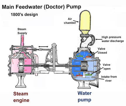 Once in operation, the Doctor pump would quickly fill all the boilers on the boat. As each boiler filled with water, other firemen would begin lighting the furnaces and tending to the job of bringing the boilers up to operating pressure. After all the boilers were filled with water, the steam from the Donkey boiler would be redirected from the Doctor pump and into the main boilers to speed their coming on line. When the main boilers built up sufficient steam pressure, the Donkey boilers fire would be drawn (literally pulling the hot coals from the furnace and extinguishing them) and the unit completely shut down. Steam for running the Doctor pump was then supplied by the main boilers. The Doctor or main feed water pump was a high volume, high pressure source of water for the boilers. It consisted of a small steam engine and a one or two piston water pump. Each stroke of the piston(s) would draw water from beneath the boat and force it through pipes into the boiler whenever the engineers opened the feed water valves. In this way the engineers could maintain the proper water level in each of the boilers simultaneously. You can imagine the trouble that system caused when a boat ran into low water and the pump sucked up tons of mud, instead of water, from the river bottom and injected it into the boilers. Many is the time steamboat's had to stop and tie up for a day while the engineers and firemen worked feverishly to clean all the mud from the pump, pipes and, boilers. As useful as Doctor pumps were, they were also complicated machines with many moving parts prone to breakdowns. Thankfully piston pumps, the only pump design known in those early years, were not the only means of getting feed water into a boiler. If simplicity and ease of operation were worth anything, the Injector would be priceless. A simple steam operated devise which sucks water from the river and literally injects it into a working boiler. Since Injectors have only one moving part (the control stem) their is little chance of a mechanical breaking down. However reliable they are, their small size limits the amount of water they can force into a boiler and yet that same reliability made them the perfect back-up for the main feed water pumps in the early years of steamboating. 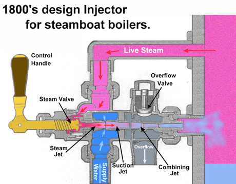 The basic, 1800's, design of Injectors consist of a set of three nozzles each of which comes close to, but does not actually connect with, the other nozzles. When the control stem is opened live steam is directed through the first or Steam Jet at speeds of 1,700 feet per second or more. This high speed jet of steam enters the second or Suction Jet and causing an ejector effect which draws water from the surrounding chamber and carries it into the Suction Jet. The receiving end of the Suction Jet is slightly larger than that of the Steam Jet to allow the free passage of water into the Suction Jet. Looking at the illustration you will notice that the walls of the Suction Jet are somewhat tapered. This tapering reduces the space available for the water thereby increasing the speed at which it is traveling. This added momentum combined with the still active steam jet forces the two into the second or Combining Jet. Once in the Combining Jet, the water and steam mix completely. Being cooled by the water, the steam looses its heat and collapses to something less than 1,000 times its original area. In combining, the steam transfers some heat and most of its momentum to the water so from that point on only water is moving through the Combining Tube and moving with terrific force. Moving with such great momentum the water easily overcomes the pressure of water in the boiler and enters that space without difficulty. You may also notice the space surrounding the Combination Tube. This is the Overflow Valve. Should the amount of water being drawn into the be to great , it will expand into this area and, when sufficient pressure develops, open the relief valve and dump the excess. Engineers paid close attention to the amount of water which occasionally came from the Overflow pipe. Should a large amount of water, and steam, start pouring from this pipe, the engineer knew that something had malfunctioned within the Injector, possibly some mud or small pebble blocking the Combining Tube. Whatever the cause, he knew he had to take quick action to keep water flowing into his boiler and preventing an explosion. Care And Feeding of a Steam Boiler - Part 2 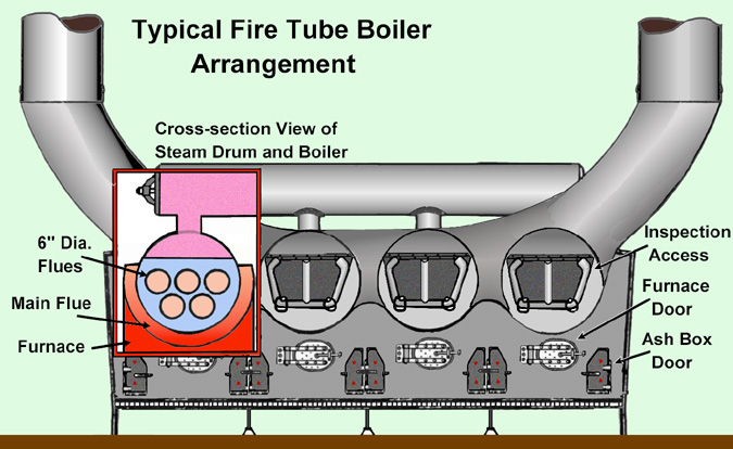
Aside from water, steam boilers need an enormous amount of combustible material to keep them working properly. Early steamboats were designed to operate on wood. Wood which was in great abundance along the eastern rives and easily harvested. Hardwoods such as Ash, Oak, Beech and Elm were called "class 1" wood. Pine, Birch and Poplar were included in "class 2" as they are softer less compact wood. The heavier and more dense hardwoods were preferred as fuel, however, class 2 wood was frequently used. Especially in later years when the supply of hardwoods grew more scarce. As a fuel, wood had two thing working in its favor. First, it was readily available along the shores of rivers. Second, it was cheap. Both extremely important items to the steamboat owners who had to make a profit with each trip the steamboat made. Aside from being both cheap and easily accessible, wood, as a fuel, had several drawbacks. It was heavy, occupied a large amount of deck space to store and required a large number of men to handle, all of whom had to be paid. Wood did not provide a uniform amount of heat in the furnaces. Different types of wood provide more, or less, heat than others. Wood is wet. Naturally wet. Nearly 1/2 of the weight of a piece of any hardwood is moisture. Even after several years of storage in a dry place wood contains nearly 20 per cent of its moisture. When a piece of firewood if tossed into a furnace it does not immediately begin to burn. For a short time the moisture in the firewood actually absorbs heat from the furnace and boils away. Then, as the wood dries, it begins to burn and provide heat to the boiler. Early steamboats carried a large supply of firewood which also took up a large amount of deck space. Space which might otherwise be used to carry cargo. Even with a full load of firewood, steamboats had to make frequent stops to "wood up" or take on more fuel. Wood also creates a large amount of ash and cinders which had to be constantly removed from the furnace Ash Box and disposed of overboard. Using wood for fuel had another drawback. As more and more trees were cut down for firewood, fewer and fewer trees were available to provide that fuel. Wood cutters had to travel further and further to find a supply of trees and that in turn drove prices up. Thankfully coal soon became widely available and economically practical. Coal burns much hotter than wood so it takes less coal to create the same amount of steam. This in turn meant longer steaming times and reduced the number of fueling stops a steamboat had to make. Coal burns cleaner than wood creating far less ash and almost no cinders. Hence the ash box required less attention by firemen. And that, from the owners point of view, meant fewer paychecks or more profits. Still, if for some reason coal was not available, the captain could always load up with wood and be on his way again. As good as coal is as a fuel, it also has its drawbacks. Coal is dirty, dusty stuff to handle which ignites easily. Even a tiny spark can ignite dry coal dust. If a spark or cigarette happened to fall on to some coal dust, and that dust was close to a coal storage bin, well it could quickly become a major blaze. A gust of wind, blowing across the open deck of a steamboat boiler room, it could kick up a cloud of coal dust. Such clouds are extremely explosive once ignited, say from a spark or the open flame in a furnace. The resulting explosion could quite, at worst, destroy the boat or, at best, set the wooden vessel on fire. But that's progress for you. Progress never seems to stop and like everything else, coal soon had a rival as the choice of fuel for steamboats as well as just about every other type of vessels. Fuel oil was again easier to store and handle than coal. It does not have the same explosive dust of coal and burns hotter per pound than coal. Considering all its characteristic, fuel oil seemed to have been the ideal fuel after which engineers had search for decades. Yes, Fuel Oil did seem to be the ultimate in fuel for boilers of all makes, models, sizes and types. Any boiler could be quickly converted to use fuel oil. Such furnaces have no Ash Box for fuel oil does not create any ash or cinders. The fuel oil furnace can, normally are, operated by automatic controls further reducing the need for firemen. The oil is cheap, readily available world wide, easy to store and requires not one person to move it from its container to the furnace. Progress, however, was still on the move and the once celebrated fuel oil was to be challenged by yet another source of heat. Uranium! Yes, atomic energy has been powering ships and electric plants for some years. And as complicated as they are, they are still nothing than modern versions of the early steam engines. 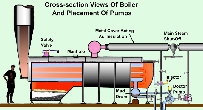
Care And Feeding of a Steam Boiler - Part 3 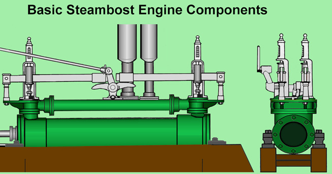
Like the vessels they propelled, river boat steam engines came in a variety of sizes. The side-wheeler Paul Jones had engines with 21 inch diameter pistons and a stroke of 7 feet. The engines on the City of Natchez used pistons 26 inches in diameter with a stroke of 10 feet. Many were smaller, much smaller however a few may have been even larger. If we take a minute to do the math, we can determine just how much steam those massive engines used. For those who don't know, or who have forgotten, the formula for determining the volume of a cylinder is (Volume = 3.1416 x (R x R) x H). For the City of Natchez engine's the answer is, 63,711 cubic inches. Sixty-three thousand seven hundred and eleven cubic inches of steam were used with each ten foot stroke of the engine. Doing a little more math we can figure out the amount of water it took to make that much steam. Water as we know, boils at 212 degrees (F). In a pot on the stove that is. When we confine the same water in a boiler under 200 pounds of pressure, it boils at 387 degrees (F). When water is converted to steam it expands 1,700 times its normal volume. Basically that means that one cubic inch of water when converted to steam will occupy 1,700 cubic inches of space. If we divide the amount of steam used in the engine by 1,700 we get 37.5 cubic inches of water. Or put another way, slightly more than 2 1/2 cups of water. Two and a half cups of water isn't very much to be sure. But that was just for one stroke of the engine. One full revolution of the paddle-wheel requires two strokes of the piston or 75 cubic inches (five cups) of water per revolution. And of course there were two engines on each steamboat so we really used 150 cubic inches or roughly 10.3 cups (2 1/2 quarts) of fresh water for each complete revolution of the paddle-wheel. Still not a tremendous amount of water is it? Okay, so now we multiply 2 1/2 quarts by the number of revolutions a paddle-wheel makes in one minute. Generally in fair weather and deep water most steamboats went as fast as they could. Getting the passengers and cargo to their destination quickly was of prime importance. So it was not uncommon to find the big paddle-wheels rotating once every six seconds. That means 2 1/2 quarts of water being used every six seconds. Multiply that by ten (10 X 2 1/2) and we find we are using 25 quarts or 6 1/4 gallons of water every minute. That's 375 gallons an hour just to keep the paddle-wheel turning and does not include the steam used by Doctor or main feedwater pump, the bilge pump, and the boats whistle. All demanded and received their fair share of steam from those hard working boilers. |
|
The Engine. What it is and How it Works
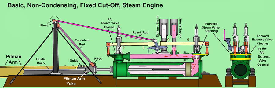
Non-condensing, Fixed Cut-Off, Steam Engine. Quite a mouthful even for those who know what it means. Lets take it one step at a time. Have you ever seen a steamboat, either in the movies or real life? Did you notice the large puffs of white steam shooting into the air from pipes near the back of the boat. Those graceful white puffs are the Exhaust Steam from each stroke of the engines. Those clouds of white are really Condensed Steam. And all that steam you see puffing into the sky is being wasted. Both early steamboat designs and railroad locomotives, are examples of "non-condensing" steam engines. A technical term meaning they do not re-use the steam. Once it has done it's work, the spent steam was vented directly into the atmosphere. A tremendous waste of both water and fuel for more water had to be pumped into the boilers and heated. Water which came from a rather muddy and cold river to boot. So what is the difference between a Non-condensing and Condensing engine? A "condensing" steam engine does not exhaust its spent steam. Instead the spent steam is piped into a devise which, like a car radiator, cools the steam turning it back in to liquid water (condensing the steam). That still very hot water is pumped back into the boilers where it is reheated and reused. Since the returning water is still very hot it requires less heat to bring it back up to boiling temperature. A big savings in fuel and boiler maintenance, for this reused water is free of mud and dirt like normal river water. The term "fixed cut-off" refers to the method of opening and closing the steam valves. In a fixed cut-off engine the rate at which the steam valves open and close is "fixed." Not adjustable, just open or closed at a given rate. Later designs included an additional device which allowed the valves to be controlled. That in turn allowed the engineers more control over the rate steam was used by the engines. Looking at the illustration you will quickly notice that steam has entered the cylinder by way of the Steam Supply Valve at the right end and is beginning to push the piston to the left. The piston is connected to the drive shaft which in turn is connected to the Pitman Arm Yoke. A yoke is a type of hinge shaped something like a tuning fork or the letter 'Y'. There is a large bearing or pin which runs between the two ends of the 'Y' which connects the Pitman Arm to the Yoke. The other end of the Pitman Arm is connected to a crank on the paddle-wheel and forces the wheel to turn. So, steam pushes on the piston, which moves the drive shaft, which moves the Pitman Arm yoke, which moves the Pitman Arm which moves the paddle-wheel crank causing the paddle-wheel to turn. Simple! Also connected to the pitman arm yoke is the Pendulum Rod which received its name from the way it rocks back and forth like the pendulum in a grandfather clock. As the Pitman Arm Yoke moves, the Pendulum Rod moves with it sliding through a hollow, pipe like, guide. As the Pendulum Rod moves back and forth with the yoke, it moves the Reach Rod in the opposite direction. If the pitman arm yoke is moving aft (left) the reach rod is moving forward (right). The reach rod in turn is connected to the Reach Rod Cam located on the engine. As the reach rod moves it makes the reach rod cam oscillate or rock back and forth. As the cam slowly oscillates it raises one side which lifts a Lever. The upward movement of this Lever opens a valve at the end of the cylinder allowing steam to flow. At the same time the other side of the cam moves downward lowering and closing the valve at the opposite end of the engine. If this did not happen there would be live steam pushing on both sides of the piston and it would not move. What is not obvious from the illustration is that there are four (4) levers and four (4) valves. Two steam supply valves and two exhaust valves. One of each on either end of the engine and mounted directly across from each other. A series of small cams and levers connects the reach rod cam to Exhaust Cam on the other side of the engine which, as its name implies, operates the Exhaust Steam Valves. And just like the supply valves, one of them is always closed. When the Drive shaft reaches its furthest point of travel, the pendulum rod has swung its full arch which pushed the Reach Rod causing the Reach Rod Cam to rotate as far as it can go. And that is one half (1/2) turn of the paddle-wheel. As the wheel continues to turn, the pitman arm begins to move in the opposite direction which makes the pendulum rod reverse its swing, which in turn pulls on the reach rod, which causes the Reach Rod Cam to reverse it oscillation. This closes the previously open supply valve and opens the other (previously closed) supply valve. Steam not flows into the opposite end of the cylinder forcing the piston to move backward. Pulling instead of pushing the drive shaft and pitman arm along with it. One complete rotation of the paddle wheel
Although both the steam supply and exhaust valves sit on top of a common manifold, they are in no way connected. Separate pipes deliver live steam to, and remove spent steam from, the engine. The metal case surrounding the steam pipes was an early attempt at insulation. Keeping the steam HOT was (still is) a very important factor in making a steam engine run properly. By 1889 the steam driven turbine engine was being perfected and the fate of the piston engine sealed. Smaller, less complicated, reliable and more efficient the turbine engine was soon to replace almost every piston steam engine in maritime service. Summary of Steam Engine History by Michael Glenn A good number of people were involved with experiments with steam-powered vessels: Samuel Morey among them. Many of these people have their supporters and like to tout them as the true inventors of the steamboats-many regional prejudices withstanding. Most people in the U.S. learned that Robert Fulton invented the steamboat. the date was August 7, 1807. Imagine how it must have been-paddlewheels noisily creaking and splashing, crude steam engine shaking the deck, black sooty smoke belching from the chimney with sparks falling all around, people on board chattering with excitement as the vessel slowly moved up the Hudson River against the current and without a sail. Fulton's steamboat went from New York to Albany a 150-mile trip taking 32 hours at an average speed of about 5 miles-per-hour. She was called the CLERMONT. Her first historic journey was in 1807, Fulton advertised his boat to the public as THE NORTH RIVER STEAMBOAT. On September 4,1807, the vessel made her first voyage with commercial paying passengers up the NORTH RIVER. After a brief running season, Fulton's NORTH RIVER STEAMBOAT was completely rebuilt in spring of 1808. Design flaws were remedied and she was launched again, for all practical purposes, a new, stronger and larger boat. By the summer of 1808 the boat was such a success that it could not accommodate all of the people who wanted to passage on her. By march of 1809, the NORTH RIVER had made a clear profit of $16,000. On December 3, 1787 James Rumsey's steam-powered water-jet craft ran successfully for about two hours on the Potomac River averaging about 3 miles-per-hour. Before that, in 1776,Frenchman Marquis de Jouffroy d'Addans ran a steamboat on the saone River at Lyons (France) - moving under it's own power for 15 minutes before it's bottom gave way. In 1789, Englishman William Symington's small steam-powered sidewheel vessel ran briefly on the Forth and clyde canal between 5-7 miles-per-hour. In 1792, American Elijah Ormsbee's duck-foot steam paddler ran briefly out of Windsor's cove at Narragsett Bay, making 3 miles-per-hour. American samuel Morey built and ran a stern-wheel powered vessel, running Hartford to New york at about 5 miles per-hour in 1793. Back in England, William Symington ran his steam-powered sidewheel tug, the CHAROTTE DUNDAS, on the Forth and Clyde while towing two barges, each of 70 tons. In March of 1803, his vessel ran 19 1/2 miles in a 6-hour period without incident.But the credit went to Mr. Symington. A year later, American Robert L. Stevens ran steam-powered, screw-propelled vessel from New York to Hoboken. The truth is that none of the individual detail that made up Fulton's invention's where his own - they were all borrowed from others. There were many steam-boat inventors before Fulton who actually built the first working steamboat. there was - Jouffroy in 1776 - Rumsey in 1787 - Fitch in 1787 and 1790 - Symington in 1789 and 1803 - Ormsbee in 1792 - Morey in 1793 and stevens in 1804. While these vessels actually worked, they were all "experiments." Even Fitch's remarkably effective, after covering several thousand miles on a regular schedule, failed after less than a year of operation - a commercial failure. After Fitch's achievement, steamboat development stood virtually still for over 15 years. The English claimed that William Symington was the true inventor of the steamboat. After abandoning successful experiments in 1789, he received financial support from Thomas lord dundas of kerse to build a steam-powered tug for use on his canal. In march of 1803, the sidewheel CHARLOTTE DUNDAS would have successfully introduced steam navigation to England and the world. It probably could have, but it didn't, Mr.Symington's efforts pretty much ended there. Fulton carefully studied all of those who preceded him and combined all of their successes and made a steamboat that not only worked, but was commercially successful. Not a single part of his NORTH RIVER STEAMBOAT was his own invention - although he patented improvements on much of the machinery. His was, without question, the first useful steamboat. His vessel was the product of accumulated knowledge, not an isolated phenomenon as was those that preceded his. he took the best from each of the others, combining and improving on all of the pieces until the result of this synergism was success. The time was right. Acceptance was at hand. The boat worked. People could ride on it and did. nit paid it's own way - no longer an experiment or demonstration. After the NORTH RIVER STEAMBOAT began running, steamboats began to proliferate. Success breeding success - the ultimate testament. Those who came before Fulton, however brilliant and worthy, were only martyrs in the cause, because the times were not yet ready. Because of these reasons, Fulton deserves credit for being the inventor of the first successful steamboat. No, he wasn't the first to make a boat move under the power of steam. Yet, it was not until after his first successful trip in 1807 that we saw the fruit of his genius - his ability to improve upon his designs and continue at will to build effective steamboats. The principles of his success were so clear and well stated that others were able to follow his lead and repeat his efforts. Steamboats then proliferated everywhere. It has ceased being a philosophical experiment and had become a practical and reliable methods of transportation. Fulton was the right man at the right time place at the right time. Fulton was the true inventor of the steamboat. Editor's note: Not everybody agrees that Fulton was the true inventor of the steamboat. For more information about other first inventors of the steamboat, see: Who Built the First Steamboat? (at this site). 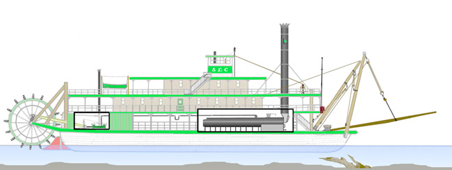
This illustration shows where the boilers are inside a steamboat. For more info. visit the steam power section of HowStuffWorks.com 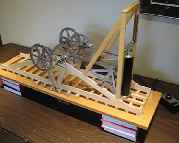
Pete Baker sent this video and said: "Here's a Youtube link for the prototype engine that Fulton's Followers are working on. David has done a remarkable job on building what you see. The final version will be donated to the Clermont Historic Site in Germantown, NY for use in their Visitors Center as a hands on display." Click here to go to Youtube. |